Any of you who have worked with VPLS or NG-MVPNs are likely already familiar with using Point-to-Multipoint (P2MP) LSPs to get traffic from a single ingress PE to multiple egress PEs. The reason that P2MP LSPs are desired in these cases is that it can reduce unnecessary replication by doing so only where absolutely required, for example where a given P2MP LSP must diverge in order to reach two different PEs.
However, typically the sub-LSPs which are part of a given P2MP LSP traverse the shortest-path from ingress to egress based on whatever user defined constraints have been configured. While this is fine for many applications, additional optimizations might be required such that additional bandwidth savings can be realized.
We will take a look at something called a Steiner-Tree which can help the network operator to realize these additional savings, when warranted, reducing the overall bandwidth used in the network and fundamentally changing the way in which paths are computed.
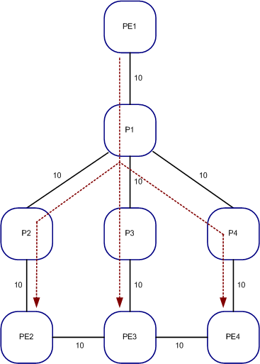
Let’s start by taking a look at a simple example in which RSVP is used to signal a particular P2MP LSP, but no constraints are defined. All the links in this network have a metric of 10. In this case, the sub-LSPs will simply traverse along the shortest path in the network, as can be seen in the diagram below.
Here we see a P2MP LSP where PE1 is the ingress PE and PE2, PE3, and PE4 are all egress nodes. Since no constraints have been defined the calculated ERO for each of the sub-LSPs will follow along the shortest path where we can see one sub-LSP taking the PE-P1-P2-PE2 path, another is taking the PE1-P1-P3-PE3 path, and the third is taking the PE1-P1-P4-PE4 path. In this case, each sub-LSP has a total end-to-end cost of 30.

Under many circumstances this type of tree would be perfectly acceptable, especially when the end-goal is the minimize end-to-end latency, however there are other cases where we may want to introduce additional hops in an effort to reduce overall bandwidth utilization. This is where the concept of a minimum-cost tree, otherwise known as a Steiner Tree, comes into play.
This may seem counter-intuitive at first; after all, doesn’t a shortest-path tree attempt to minimize costs? The answer is yes, but it usually only does so by looking at costs in terms of end-to-end metrics or hops through a network. Once you understand the mechanics of the Steiner Tree algorithm, and how it attempts to minimize the total number of interconnects, it starts to make more sense.
According to Wikipedia, “the Steiner tree problem, or the minimum Steiner tree problem, named after Jakob Steiner, is a problem in combinatorial optimization, which may be formulated in a number of settings, with the common part being that it is required to find the shortest interconnect for a given set of objects”.
That’s a pretty fancy way of saying it’s attempting to optimize the path to be the shortest path possible while at the same time reducing the total number of interconnects between all devices to only those that are absolutely required.
Steiner Tree optimizations are very useful where an ingress PE must send large amounts of data to multiple PEs and it is preferable to ensure that overall bandwidth utilization is reduced, perhaps because of usage-based billing scenarios which require that overall circuit utilization be reduced as much as possible in order to save money.
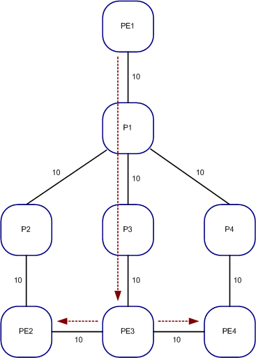
Let’s take a look at an example, once again using the same network as before, but this time performing a Steiner Tree optimization whereby cost is measured in terms of overall bandwidth utilization. In this case we still see that we have the requirement to build the P2MP LSP from PE1 to PE2, PE3, and PE4. However, this time we are going to compute an ERO such that replication will only take place where absolutely necessary in order to reduce the total number of interconnects and hence overall bandwidth utilization.
After performing a Steiner Tree path computation, we determine that PE3 is a more logical choice to perform the replication to PE2 and PE4, even though it increases the overall end-to-end metric cost to 40. The reason for this is we have now effectively eliminated the bandwidth utilization on the P1-P2, P2-PE2, P1-P4, and P4-PE4 links. In effect, we’ve gone from utilizing bandwidth across seven links to only five. If the P2MP LSP was servicing a 100 Mbps video stream, we have just effectively reduced overall bandwidth utilization on the network as a whole by 200 Mbps.

One of the interesting side-effects of this approach is that we now see that PE3 is not only an egress node, but it is now also a transit node as well (for the sub-LSPs terminating at PE2 and PE4). Due to this, we’ll also see that in these types of scenarios the Penultimate Hop Popping (PHP) behavior is different on P3 in that we don’t want it popping the outer label before sending frames to PE3 since PE3 may need to accommodate labeled packets heading to PE2 or PE3. We will cover some of this in a subsequent article on the signaling mechanisms inherent in P2MP LSPs and some of the changes to the behavior in MPLS forwarding state.
Path computation for P2MP LSPs can be complex, especially when the goal is create Steiner Trees. The reason for this added complexity when computing Steiner Trees is that sub-LSP placement has a direct correlation with other sub-LSPs, which is contrary to what happens when shortest-path trees are calculated where each sub-LSP may be signaled along their own unique path without regard to the placement of other sub-LSPs.
As with traditional LSPs, similar methods of determining the paths through the network and hence the ERO can be used, i.e. manual, offline computation.
The easiest approach would be to use constructs like Link Coloring (Affinity Groups for you Cisco wonks) to influence path selection, for example, by coloring the PE1-P1, P1-P3, P3-PE3, PE3-PE2, and PE3-PE4 links with an included color, or coloring the remaining links with a different color and excluding that color from the LSP configuration.
However, this approach is merely a trick. We are feeding elements into the CSPF algorithm such that the shortest path which is calculated essentially mimics that of a Steiner Tree. In other words, it’s not a true Steiner Tree calculation because the goal was not to reduce the total number of interconnects, but rather to only utilize links of an included color.
Furthermore, such an approach doesn’t easily accommodate failure scenarios in which PE3 may go down, because even though Fast Reroute or Link/Node Protection may be desired, if the remaining links do not have the included colors they may be unable to compute an ERO for signaling.
Workarounds to this approach are to configure your Fast Reroute Detours or your Link/Node Protection Bypass LSPs to have more relaxed constraints, such that any potential path might be used. However, more commonly what you’ll see is that some type of additional computations might be performed using traditional offline approaches (using modeling tools such as those provided by vendors such as WANDL, OPNET, or Cariden) which factors both steady-state as well as failure scenarios to assist the operator in determining optimal placement of all elements.
An interesting side-note is that there are some pretty significant developments underway whereby online computation can be performed in such a way as to optimize all P2MP LSPs network-wide, using something known as Path Computation Elements (PCEs). These are essentially any entity which is capable of performing path computation for any set of paths throughout a network by applying various constraints. It is something that looks to be especially useful in large carrier networks consisting of many LSPs, and especially so in the case of Steiner Tree P2MP LSPs where the sub-LSP placement is highly dependent on others. See the charter of the PCE Working Group in the IETF for more information on this and other related developments.
As a side note, it should be fairly evident that in order to perform path optimizations on anything other than shortest-path trees (i.e. Steiner Trees or any other type of tree based on user-defined constraints), RSVP signaling must be used in order to signal a path along the computed ERO. LDP certainly can be used to build P2MP LSPs (aka mLDP), however much like traditional LSPs built via LDP, the path follows the traditional IGP path.
Stay tuned as we will cover more exciting articles on P2MP LSPs and some of the other underpinnings behind many of the next generation MPLS services being commonly deployed…

A good article about P2MP RSVP TE, that can be used in the forwarding plane for NG MVPN with MP iBGP in the signaling plane but you know it ….
Thanks for the post, great stuff here.
Thanks Hans, thanks Giuseppe. Very much appreciate you stopping by.
Giuseppe, were you referring to my article or are you referencing some other article?
Excellent write-up, Stefan! I also believe an RSVP-TE signaled P2MP LSP is the solution for the VPLS ingress replication issue.
Do you know if the auto-bandwidth option for P2MP LSP & its sub-LSPs has been implemented by Juniper? I know we could always use one of the offline tools to manage bandwidth, but that doesn’t scale in large networks and becomes management overhead.
Great work. I look forward to reading the next installment of this article.
Tariq
Interesting! Very nice article.
I’ll looking for more information about it,
Regards,
Thiago
Great article! It’s really got me thinking about the relationship between the routing algorithm and the actual business objective of delivering LSPs.
It seems to me, with the emergence of PCE and off-line planning tools like Cariden, Aria Networks, Opnet et al, that picking one algorithm for computing paths may no longer be necessary, provided there is a strategy to move towards MPLS-TE.
A single algorithm can usually optimise only one thing, maybe two if you’re lucky. And that ‘thing’ is usually fixed. You illustrate this pretty clearly: shortest-path (Dijsktra-like) optimises ‘cost’ (not true $ necessarily, but some abstracted cost), Steiner optimises ‘bandwidth’ – and depending on the true $ cost in your network, and the type of LSP being built, these approaches may approximate to a true cost-optimised solution.
But, in practice, we need to optimise, or at least set acceptable limits, on many things. True cost, individual service resilience, over-all network resilience, end-to-end delay, bandwidth utilisation… even business objectives like service delivery time.
How planning tools optimise or balance these constraints is a whole different topic, but what’s needed to allow network planners to truly meet business requirements is the ability to say ‘optimise these services for best X, minimise Y and don’t let attribute Z go above N’. The tool is then responsible for picking the best routing algorithm, performing a search, running ‘what-if’ analysis… whatever it needs to do.
Off-line tools, as distinct from PCE, tend to be compute-intensive rather than real time. As I said, this is therefore typically most suitable for MPLS-TE where the LSPs are nailed up (at least for business as usual) as a service design or fulfilment process.
My question is; Is there a bit of a chicken and egg situation here? Traffic engineered LSPs are only preferable if the planner has the tools to make the best use of them; Planners will only invest in LSP design tools if they have committed to significant investment in MPLS-TE technology.
That’s an excellent write-up. Stefan! Thank you for explaining it in an easy and lucid way.
Atif